CSCI 210: Lab 5
7-Segment
LED
Due:
11:59
PM
on
Monday,
July 12
Circuitverse
We will be using the Circuitverse website to complete this assignment. You should have received an email inviting you to the CSCI210_SU21 group on Circuitverse.org. If you did not, please use this link to join the group. To start the assignment, click on your name on the upper righthand side of the website. Go to "My Groups" and you should see "Lab 5" under assignments. Click the "Start Working" button to start the assignment. After you click "Start Working" you can click "Launch Simulator" to start creating the assignment.
You can find more details on how to use the circuitverse website here.
7-Segment Display
In this assignment, you will design a combinational logic circuit which will drive a 7-segment LED display, which looks like this:
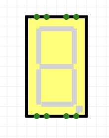
The input to circuit is a set of 4 signals a3, a2, a1, a0 representing the digits of a 4-bit binary number. The output is a set of the seven signals a, b, c, d, e, f, and g used to drive the seven segments of the LED display. When implemented correctly, your circuit will display value of the input as a hexadecimal digit on the 7 segment display. Below is the display with each segment labeled:
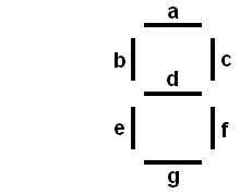
Each of the outputs can be represented as a boolean function of the four input variables. For example, if the input is 0101, then segments a, b, d, f, and g should be on (1), while c and e are off (0), forming the digit "5" on the display.
You will be creating a decoder and using it to drive the 7-segment display. You should create the decoder yourself from AND and OR gates, and not use the built in circuit-verse decoder. You will find chapter 3.4 of the book and lecture 18 to be helpful.
Implementation
You should use the following plan for implementing this lab:- Draw out all the numbers on graph paper first.
- For each of the segments a–g, write down which numbers correspond to that segment.
- Build a 4-bit decoder as a subcircuit. You MUST have your decoder as a subcircuit in order to receive full credit for this lab. Documentation for how to create a subcircuit is here.
- For each segment, create one or more OR gates (as needed), add the appropriate outputs from the decoder to the OR gate.
- Keep wires straight or right-angle turns. Pick the order the decoder outputs will go into the OR gates so as to minimize wire crossing.
- If inadvertent connections are made, undo, don't try to fix it.
Performing step 2 before step 4 is critical. You don't want to be trying to wire this up while figuring out which decoder outputs you need to OR.
Handin
Make sure to select the "save online" button to save your project. This will make your project available to us for grading.C. Taylor